
Decoding 3D Printing Infill: The Hidden Lattice Powering Modern Additive Manufacturing

Introduction to Additive Manufacturing Interiors
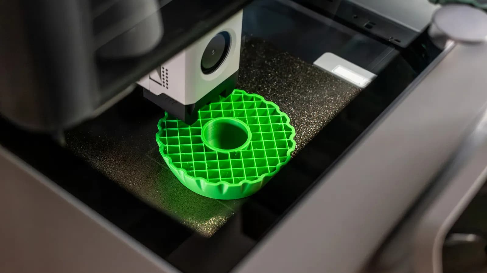
When most people observe a 3D printer in action, their eyes are invariably drawn to the exterior. The mesmerizing dance of the print head laying down precise outlines, the gradual emergence of a smooth outer shell, and the layer-by-layer rise of a physical object from a digital file capture our imagination. Yet, the true engineering marvel of modern 3D printing lies hidden beneath the surface. What happens inside the object—the invisible internal architecture known as infill—is what ultimately determines whether a printed part will withstand heavy mechanical stress or snap under the slightest pressure.
For software developers, hardware tinkerers, and engineers working with rapid prototyping, understanding how slicing software generates internal geometry is just as critical as mastering CAD design or firmware configuration. Infill settings represent a delicate optimization problem: balancing structural rigidity against material consumption, print time, and weight. Getting these parameters wrong can lead to failed prints, wasted filament, or catastrophically weak components that fail right when they are deployed in a real-world scenario.
Defining Infill and Its Core Mechanics
At its foundational level, a 3D printed object is rarely solid plastic all the way through. Printing a completely dense, solid block is generally inefficient, wasteful, and time-consuming. Instead, slicing software—the bridge between a 3D model and the printer's G-code—hollows out the interior of the model and fills it with a repeating geometric matrix. This internal lattice is what we call infill. It acts as an internal scaffolding, providing support for the top surface layers while tying the outer walls together.
The mechanics of infill are governed by two primary variables: density and pattern. Density refers to how tightly packed the internal structure is, usually expressed as a percentage ranging from a completely hollow zero percent to a fully dense one hundred percent. The pattern dictates the actual geometry of the lattice, ranging from simple grids and lines to complex, mathematically optimized structures like gyroids, cubic, and tri-hexagon patterns. Each pattern distributes mechanical loads differently across spatial dimensions, making the choice of infill a crucial engineering decision tailored to the specific application of the printed part.
Why Infill Density and Patterns Matter
The choice of infill configuration directly dictates the physical properties of the final printed object. If an engineer is designing a decorative desk accessory or a cosmetic mockup, structural integrity is a secondary concern. In such cases, a low infill density—perhaps ten to fifteen percent—combined with a fast, straightforward pattern like lines or grid is more than adequate. It saves precious filament and drastically reduces the hours required for the print job to complete.
Conversely, functional prototypes, mechanical gears, brackets, and load-bearing fixtures demand a radically different approach. These components require higher infill percentages and sophisticated patterns capable of absorbing multidirectional forces. For instance, a gyroid infill pattern is celebrated in the additive manufacturing community for its exceptional strength-to-weight ratio and its ability to distribute stress evenly across all three axes. Choosing the right combination ensures that the manufactured part behaves predictably under operational loads, bridging the gap between digital design and physical reality.
The Optimization Trilemma: Strength, Time, and Material
Working with 3D printers inevitably forces a compromise among three competing constraints: mechanical strength, fabrication time, and material consumption. Increasing infill density linearly increases the amount of plastic used and the time required for the nozzle to complete the internal pathways. For production environments or iterative prototyping sprints, unnecessary print time and wasted polymer translate directly to increased costs and slower development cycles.
Slicers have evolved sophisticated algorithms to help mitigate this trilemma. Modern software allows for variable infill densities within a single model, applying higher density only to stress concentration zones while keeping low-stress regions hollow. Developers and designers leverage these advanced slicing profiles to optimize structural performance without paying a heavy penalty in material waste or extended print durations. It is a classic optimization problem solved through computational geometry.
Common Misconceptions and Best Practices
A prevalent myth among beginners is that increasing infill density is always the best way to make a weak part stronger. In reality, the structural strength of a 3D printed object is often dictated more by its perimeter settings—known as walls or shells—than by its internal infill. Adding an extra perimeter wall or increasing top and bottom solid layers frequently yields a more durable part than cranking up the infill percentage from twenty to eighty percent, while consuming less additional filament.
Best practices in additive manufacturing dictate a methodical approach to infill selection. Designers should analyze the directional forces the object will experience in the field. If a bracket experiences twisting torque, an infill pattern with high shear resistance is necessary. If the part needs to absorb impact energy, a flexible or mathematically continuous lattice structure is preferred. Testing and iterative prototyping remain essential for validating these choices before scaling production.
The Future of Internal Geometry in Manufacturing
As additive manufacturing continues to mature, the concept of infill is evolving beyond simple repeating geometric patterns. Researchers and software engineers are developing generative design tools powered by machine learning algorithms that calculate custom internal structures tailored to the exact load paths of a specific component. These organic, bone-like internal architectures blur the line between solid manufacturing and complex lattice structures.
For the broader technology and development ecosystem, these advancements highlight the deep integration between software intelligence and physical hardware. As slicer software grows more sophisticated, the barrier to creating ultra-optimized, lightweight, and high-strength industrial parts continues to drop. Understanding the humble infill setting is no longer just a niche 3D printing trick—it is a window into the future of how physical objects will be engineered, simulated, and fabricated.
Closing Takeaway
The internal infill of a 3D print is far more than an arbitrary filler; it is a carefully calculated lattice that balances structural integrity, material cost, and production time. By mastering infill density and geometric patterns, developers and makers can unlock the true potential of additive manufacturing, turning digital concepts into robust, highly functional physical realities.
Source: engadget.com